Terrain and siting decide what a ground radar covers because a radar's view is a line-of-sight calculation before it is a performance number: hills block the beam, the Earth's curve cuts it off, and the antenna's height above local ground sets how far that line reaches. The standard 4.12-times-the-square-root formula in radar engineering references gives a horizon of only about 23 kilometers for a 30-meter mast against a zero-altitude target — a figure from Skolnik's Radar Handbook (2008 edition) that no amount of transmitter power can extend.
That arithmetic explains most of what looks mysterious about ground-based air defense. A radar with impressive published detection ranges can be blind to a low-flying aircraft ten kilometers away if a ridge sits between them, and two identical radars at different sites can defend entirely different volumes. This explainer works through the physics, then through what a siting survey actually does about it.
Why can't the radar see over the horizon?
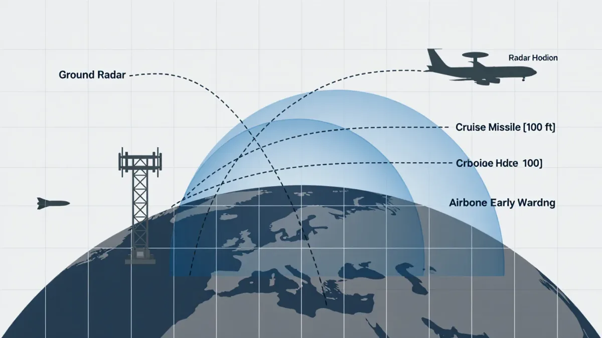
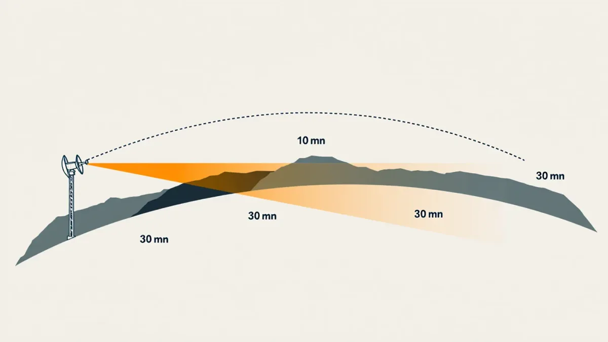
Most surveillance radars propagate in straight lines, bent slightly downward by atmospheric refraction. The distance at which the straight line from the antenna first clears the curved Earth is the radar horizon, and for standard atmospheric conditions it is calculated as 4.12 multiplied by the square root of the antenna height in meters, plus the square root of the target height, both in kilometers. Two consequences follow. First, antenna height is under the defender's control and target height is not, so the defender buys horizon with masts, towers, and hilltops. Second, the horizon against a low target is brutally short: a cruise missile at 25 meters altitude stays below the horizon of a 30-meter radar until roughly 32 kilometers out.
At 4.12 times the square root of height in meters, a 100-meter hill buys about 41 kilometers of horizon against a sea-skimming target — versus 13 kilometers for a 10-meter antenna on flat ground.
Over-the-horizon techniques that bend or bounce the beam beyond this limit exist, but they are specialized, low-resolution systems; the overwhelming majority of surveillance radars live entirely inside the line-of-sight box.
How does terrain masking carve holes in coverage?
Between the horizon and the radar sit whatever the terrain puts there. A ridgeline within the beam's path throws a shadow wedge behind it — the radar energy cannot pass through rock, so everything in the blocked sector below the ridge crest is invisible. Siting literature calls this terrain masking, and its geometry is unforgiving: a ridge 5 kilometers away and 200 meters high blinds the radar to all low-altitude approaches behind it, out to where the line of sight clears the crest.
Masking interacts with clutter. Ground returns from hillsides, buildings, and vegetation raise the noise floor in specific sectors, and moving-target-indicator processing suppresses targets whose Doppler signatures resemble the local clutter. A helicopter hovering near a ridgeline, or a slow drone drifting against a rocky background, can sit inside a strong-clutter sector and effectively disappear even though it is technically within line of sight. Detection range figures published by manufacturers assume clean conditions that no real site provides in every direction.
What does a siting survey actually involve?
Choosing a radar site is a structured engineering exercise, and its steps appear in openly taught air-defense planning material.
- Map the threat directions. Coverage is optimized toward the avenues a low-flying attacker would use — valleys, coastlines, border corridors — rather than toward geometric perfection.
- Run line-of-sight studies. Digital terrain models, or in older practice gridded maps and profile boards, are used to compute the masked sectors and horizon distances for candidate positions.
- Weigh horizon against masking. A mountaintop maximizes horizon but can create deep shadow wedges behind it and complicate access, power, and defense of the site itself.
- Check the electromagnetic environment. Interference from other emitters, multipath over flat or water surfaces, and anomalous propagation all change what the site actually delivers.
- Plan for survivability. The best electromagnetic site that is trivially targetable is a bad site; dispersal and cover interact with coverage in every real deployment.
The output is a coverage diagram — usually a polar plot with altitude floors drawn per sector — that states honestly where the radar sees and where it does not. Both halves matter; the second half is what an attacker plans around.
Why does antenna height buy so much?
Because the horizon formula is a square root, early gains are the cheapest. Raising an antenna from 10 to 40 meters adds about 10 kilometers of horizon against a ground-level target; raising it from 40 to 90 meters adds only about 7 more. This is why mobile systems accept modest masts while fixed installations chase elevation — and why the elevation of the ground under the antenna matters more than the mast above it.
| Antenna height | Horizon, flat target | Horizon vs 25 m cruise missile |
|---|---|---|
| 10 m | ~13 km | ~29 km |
| 30 m | ~23 km | ~35 km |
| 100 m | ~41 km | ~47 km |
All figures are the standard-atmosphere calculation from Skolnik's Radar Handbook; they describe physics, not any specific radar's detection performance. Detection range can be shorter than the horizon if the target's radar cross-section is small, but it can never be longer than the geometry allows.
What do defenders do about unavoidable shadow zones?
First, they measure them. Coverage surveys — sometimes verified with instrumented flights that fly the approaches and record where the radar holds them — turn guesswork into diagrams. Second, they overlap. Two radars sited several kilometers apart shadow each other's wedges; a ridge that blinds one site is behind the other's clear sector. Third, they add sensors built for the gaps: low-altitude radars placed forward in the masked corridors, or the passive and acoustic sensors that modern integrated systems increasingly carry. U.S. Army doctrine for short-range air defense openly describes this pattern of mutually supporting sensors rather than one tall answer.
Fourth, they accept residual risk and shape tactics around it. Every coverage diagram in every air force contains sectors where detection depends on the target cooperating — climbing above the ridge line, switching on a transponder, moving fast enough to be seen. Honest coverage planning is mostly the discipline of knowing which sectors those are.
What do weather and the atmosphere change?
More than most coverage summaries admit. The horizon formula assumes standard refraction; non-standard conditions bend it either way. Temperature inversions over cold sea or desert floors cause ducting, in which the beam curves down toward the surface and radar sees far beyond the nominal horizon — while targets above the duct may vanish. Under sub-refraction the opposite happens and the horizon contracts. Radar engineers document both effects, and they are why a coverage diagram drawn for standard conditions is an average, not a promise.
Multipath is the second atmospheric-adjacent effect, and it bites hardest over flat terrain and water. Energy arriving at the target by two routes — direct and reflected off the surface — interferes, creating lobes of strong and weak detection stacked in altitude. A low-altitude target sitting in a null can be invisible at ranges where it should be trivially detectable, then pop into view a few hundred meters higher. Height-finding radars and diverse sensor placements are the classic mitigations, but no siting choice eliminates the physics.
How can a reader tell whether a coverage claim is credible?
Look for three things. Whether the figure states a target altitude and radar cross-section, because "250 kilometers" against a head-on airliner and against a small drone are different sentences. Whether the horizon math is consistent with the stated antenna height. And whether the source is the manufacturer's brochure or an independent analysis — the manufacturer is the attributed source of its own numbers, never independent verification. Where none of these can be checked, publicly available sources do not establish the claim, and any coverage diagram should be read as the defender's best engineering estimate, not a verified fact.